Introduction
As renewable energy becomes an increasingly important part of modern power systems, microgrids must be able to accommodate changing solar power output while maintaining stable and reliable operation. However, fluctuations in solar irradiance, temperature variations, and changing photovoltaic (PV) operating conditions can introduce challenges for inverter performance, DC bus regulation, and energy management.
For engineers developing and validating microgrid systems, reproducing these operating conditions in a controlled laboratory environment is essential. A
bidirectional DC power supply, such as the ANEVH(F) series, can support microgrid inverter testing by providing programmable DC power and, where supported by the system configuration, absorbing energy during bidirectional operation.
By simulating controlled DC-side operating conditions, engineers can evaluate inverter behavior, investigate transient responses, and improve the repeatability of solar microgrid tests before deploying equipment in real-world applications.
1. Why Simulate Solar Power Fluctuations in Microgrid Testing?
Solar photovoltaic systems do not generate constant power. Their output changes with environmental conditions, including cloud cover, solar irradiance, module temperature, and shading.
These variations affect the DC power available at the inverter input and can influence the performance of the wider microgrid.
Common challenges include:
- Fluctuating DC input power: Rapid changes in available solar power can affect inverter operating points and power output.
- DC bus voltage stability: Variations in power generation and consumption can introduce voltage deviations within the DC subsystem.
- Power conversion performance: Inverters must operate efficiently and respond appropriately across different input conditions.
- Energy management coordination: Microgrid controllers must coordinate generation, battery storage, and loads as renewable output changes.
- Transient response: Sudden changes in operating conditions can reveal control limitations that may not be apparent during steady-state testing.
Testing under controlled conditions helps engineers identify these challenges, evaluate equipment behavior, and refine system parameters before field deployment.
2. The Role of Bidirectional DC Power Supplies in PV Inverter Testing
A bidirectional DC power supply combines power-sourcing and power-absorbing capabilities within a compatible power conversion system. Depending on its specifications and operating configuration, it can supply programmable DC power to a device under test and absorb DC power flowing back from that device.
In solar microgrid research, this capability can support several testing scenarios.
Programmable DC input simulation
A programmable DC source can reproduce selected voltage and current operating points to represent different PV-side conditions. Engineers can define test sequences that include changes in input voltage, operating point, and available power, subject to the equipment's ratings and control capabilities.
This allows repeatable evaluation of inverter performance without relying exclusively on outdoor solar conditions.
Controlled source and sink operation
When the test setup supports bidirectional energy flow, the power supply can operate in source or sink mode as required by the test scenario.
Source operation can provide energy to the inverter's DC input. Sink operation can absorb energy returned by compatible equipment, provided that the voltage, current, power, and control requirements are satisfied.
This functionality can help create more flexible test environments for power converters and DC energy systems.
Repeatable laboratory testing
Outdoor PV testing is influenced by changing weather, time of day, and installation conditions. A programmable DC test system enables engineers to repeat defined operating profiles and compare results under consistent conditions.
Repeatability is especially useful when evaluating firmware updates, comparing inverter control strategies, or investigating unexpected responses.
3. How to Simulate Solar Power Fluctuations with an ANEVH(F) Bidirectional DC Power Supply
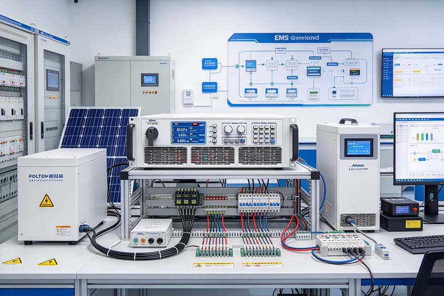
The ANEVH(F) bidirectional DC power supply can be considered part of a laboratory test platform for evaluating solar inverter behavior. The exact test methods will depend on the selected model, available operating modes, power ratings, and programming interfaces.
A typical test workflow involves the following steps.
Step 1: Define the PV inverter operating conditions
Identify the inverter's allowable DC input voltage range, maximum input current, power rating, and relevant operating limits.
Establish the conditions that the test needs to reproduce, such as:
- Stable solar generation under consistent irradiance.
- Reduced available solar power during partial cloud cover.
- Rapid changes in the PV operating point.
- Low-power operation near the inverter's minimum operating threshold.
- Recovery from a temporary reduction in available input power.
Use manufacturer documentation and the intended test objectives to define safe operating limits.
Step 2: Configure the DC power test system
Connect the bidirectional DC power supply to the inverter's DC input using a properly rated test setup and appropriate protection.
Configure the voltage and current limits, power limits, control mode, and operating sequence according to the equipment manuals. Confirm that the supply's output range matches the inverter's input requirements.
If the inverter includes a maximum power point tracking (MPPT) function, determine whether the test objective requires a PV simulator with programmable current-voltage characteristics. A conventional programmable DC source does not automatically reproduce the full nonlinear behavior of a photovoltaic array.
Step 3: Establish a steady-state baseline
Begin with a stable DC operating point within the inverter's permitted input range.
Record relevant measurements, including:
- DC input voltage and current.
- DC input power.
- AC output power, where applicable.
- DC bus voltage, if accessible.
- Conversion efficiency, where measurement accuracy and test boundaries permit.
- Relevant alarms, protection events, and operating status.
This baseline provides a reference for comparison with subsequent dynamic tests.
Step 4: Apply programmed power variations
Introduce controlled changes in the DC input conditions to represent selected solar-generation scenarios.
For example, a test sequence could include:
- Establishing a steady-state operating point.
- Reducing the available DC input power.
- Holding the reduced operating point for a defined interval.
- Increasing the available power toward the initial condition.
- Repeating the sequence to assess consistency.
Where supported by the power supply and test controller, automate these transitions to improve repeatability.
For accurate PV behavior simulation, use an appropriate PV simulator or a power supply with the necessary PV characteristic emulation functions. Ensure that the programmed profiles are consistent with the inverter's input characteristics and test requirements.
Step 5: Evaluate inverter response
Monitor how the inverter responds to the programmed changes.
Key parameters may include DC voltage deviation, AC power response, settling time, overshoot, oscillation, and protection behavior. The specific acceptance criteria should be based on the inverter's design requirements and the applicable test standards.
If the inverter is connected to a microgrid controller or energy storage system, additional measurements can help reveal how the wider system responds to changes in solar generation.
Step 6: Analyze and document results
Compare measured responses with the steady-state baseline and the expected system behavior.
Look for issues such as excessive DC voltage deviation, unstable control behavior, delayed power response, unexpected shutdowns, or inconsistent results across repeated tests.
Document the operating conditions, equipment configuration, test sequence, measurement methods, and observed results. This creates a reproducible basis for further engineering improvements.
4. Key Microgrid Inverter Tests Enabled by Programmable DC Power
A well-designed laboratory test plan can cover several aspects of solar inverter performance.
DC input operating-range testing
Evaluate inverter operation across selected DC voltage and power levels. This helps establish whether the inverter performs as expected within its specified operating range.
Dynamic response testing
Apply controlled changes in DC input conditions and measure the inverter's response. This can help identify transient limitations and assess control stability.
MPPT performance evaluation
Assess how effectively the inverter tracks the maximum power point under changing PV conditions. This test requires a suitable PV simulator or another setup capable of reproducing the required PV current-voltage characteristics; simple voltage programming alone may not be sufficient.
DC bus stability assessment
For systems with an accessible DC bus, observe voltage behavior during changes in generation or load. The results can help engineers investigate the interaction between DC bus regulation, inverter controls, and energy storage.
Protection and recovery testing
Evaluate the inverter's behavior during defined operating-limit events and its recovery when normal conditions return. These tests should follow the equipment manufacturer’s procedures and applicable safety requirements.
5. Benefits of Using ANEVH(F) in a Solar Microgrid Test Platform
When its specifications align with the application, a bidirectional DC power supply can offer several advantages for inverter research and development.
Greater test repeatability
Programmable operating conditions help engineers reproduce the same input sequence across multiple test runs, making performance comparisons more meaningful.
Flexible power-flow testing
Bidirectional source and sink operation can support test scenarios involving energy absorption, provided the test equipment and system topology are designed for that purpose.
More comprehensive inverter evaluation
Controlled DC-side testing allows engineers to investigate steady-state operation, transient response, and selected abnormal operating conditions without relying entirely on natural solar fluctuations.
Potential energy recovery
If the system supports regenerative operation and the installation provides a compatible energy-return path, absorbed power may be returned to the supply network rather than dissipated as heat. Actual energy savings depend on the equipment's efficiency, operating profile, and installation.
Support for automated test workflows
If the selected ANEVH(F) model provides suitable remote-control interfaces, it can be incorporated into automated test sequences for improved consistency, data collection, and laboratory productivity.
The suitability of these benefits depends on the actual ANEVH(F) configuration. Verify the model's specifications, control functions, and regeneration capability before designing the test system.
6. Important Considerations When Selecting a Bidirectional DC Power Supply
Not every bidirectional DC power supply can fully simulate a solar photovoltaic array. Engineers should assess the following requirements before selecting equipment for PV inverter testing.
- Voltage and current range: Confirm compatibility with the inverter's DC input requirements.
- Source and sink ratings: Check the allowable power and current in both directions, including any operating limitations.
- Dynamic performance: Evaluate programming speed, response time, and measurement bandwidth against the test objectives.
- PV simulation capability: Determine whether the application requires programmable PV current-voltage curves or MPPT-oriented simulation.
- Control and communication: Verify compatibility with the intended test automation software and laboratory instruments.
- Protection and safety: Review overvoltage, overcurrent, overtemperature, isolation, grounding, and emergency shutdown requirements.
- Regenerative operation: Confirm whether energy can be returned to the grid or another approved energy path and what infrastructure is required.
- Test-system integration: Consider compatibility with DC measurement instruments, AC grid simulators, electronic loads, battery simulators, and microgrid controllers.
Evaluating these factors helps ensure that the selected power supply meets the technical demands of the intended test program.
Conclusion
Simulating solar power fluctuations is an important part of validating photovoltaic inverters and improving microgrid reliability. By reproducing controlled DC-side operating conditions, engineers can evaluate inverter response, investigate control behavior, and develop repeatable test procedures.
A bidirectional DC power supply such as the ANEVH(F) can contribute to this process through programmable DC power and, where supported, bidirectional energy handling. When integrated with appropriate measurement equipment, control software, and PV simulation capabilities, it can form part of a flexible laboratory platform for solar inverter and microgrid research.
For engineers planning a new test bench, the key is to match the power supply's actual capabilities to the inverter's operating requirements and the intended test scenarios. This ensures that laboratory results are meaningful, repeatable, and relevant to real-world solar microgrid performance.



 TEL:+86 532 83995188
 PHONE:+86 177 5322 5039
 E-MAIL:ainuo@ainuo.com
 ADDRESS:No. 134 Zhuzhou Rd, Laoshan District, Qingdao, China